
Status: Repaired
Category: Test Equipment Repair
Device: Tektronix TDS220 Digital Oscilloscope
Introduction
Today’s patient was a Tektronix TDS220.
Despite being over two decades old, the TDS220 remains one of the most common oscilloscopes found on repair benches around the world. It is old enough to have problems, but good enough that throwing it away would be a waste.
The oscilloscope arrived with two obvious issues.
Symptoms
- Severe display flickering
- Excessive noise visible on both channels
- Noise present even with no probes connected
The display problem looked annoying.

The noise problem looked suspicious.
Initial Thoughts
The display fault seemed likely to be one of the usual suspects:
- LCD flex cable issues
- Cracked solder joints
- Aging display circuitry
The channel noise pointed somewhere else entirely.
My first guess was the power supply.
After all, this oscilloscope is old enough to legally order a beer in some countries.
Baseline Measurements
Before taking anything apart, I wanted numbers.
With both channels configured to:
100mV/div
25µs/div
the scope showed approximately:
~70mV noiseeven with nothing connected.
Not exactly confidence inspiring.
Opening the Patient
Getting inside a TDS220 is one of those jobs that sounds easy until you actually start doing it.
Two screws come out quickly.
Then come the plastic clips.
Lots of plastic clips.
The kind that make you wonder whether the engineer who designed them secretly hated service technicians.
After a careful disassembly, the internals revealed three main assemblies:
- Power supply
- Display assembly
- Mainboard
Thankfully, the modular construction makes troubleshooting relatively straightforward once everything is accessible.
Display Investigation
The display assembly came out first.
I inspected:
- LCD module
- Flex cable
- Connectors
- Solder joints
Nothing looked damaged.
No corrosion.
No cracked joints.
No obvious failures.
Since the display was already on the bench, I reflowed several suspicious-looking solder connections and reassembled the unit for a quick test.
To my surprise, the display came back to life.
No flickering.
No instability.
Problem solved?
Not quite.
A few minutes later the flickering returned.
The oscilloscope had successfully lied to me.
Recapping the Power Supply
With the display temporarily ruled out, attention shifted toward the power supply.
None of the capacitors looked visibly damaged.
No bulging.
No leaking.
No explosions.
Just twenty-plus years of existence.
That alone was reason enough.
The entire PSU received fresh capacitors:
| Quantity | Value |
|---|---|
| 3× | 2200µF / 6.3V |
| 3× | 22µF / 35V |
| 1× | 1000µF / 6.3V |
| 1× | 470µF / 6.3V |
| 1× | 2.2µF / 50V |
| 1× | 4.7µF / 50V |
| 1× | 47µF / 25V |
| 1× | 47µF / 400V |
After the recap, the oscilloscope powered on normally.

The display immediately started flickering again.
Back to square one.
The Real Fault
At this point I stopped looking at what was broken and started looking at what had changed.
The display had briefly worked after the earlier soldering work.
Why?
The answer was probably heat.
While working on the display assembly I had unknowingly warmed components near the LCD circuitry.
Time for an experiment.
Using a hot air station, I selectively heated components around the display section.
The result was immediate.
The display stabilized.
The flickering disappeared.
The suspect list suddenly became very short.
Several tantalum capacitors located near the display circuitry appeared to be temperature sensitive and no longer operating correctly.
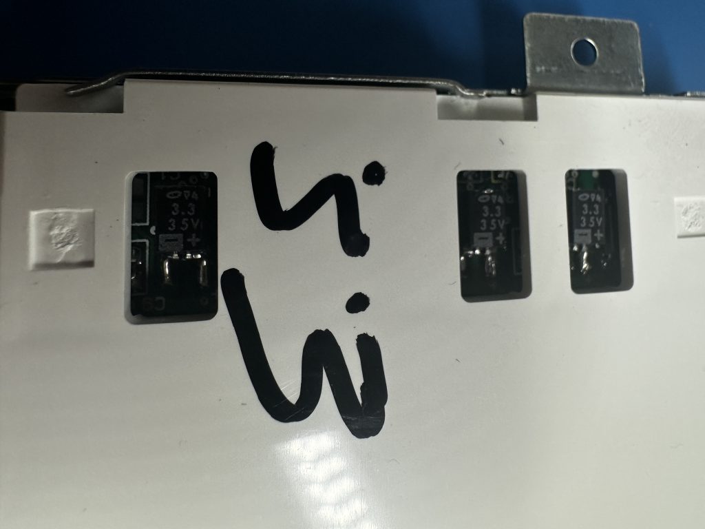
Three capacitors were replaced:
3 × 3.3µF / 35VReplacement parts were unavailable locally, so:
3 × 4.7µF / 35Vwere installed instead.
The oscilloscope showed no objections.
The flickering disappeared completely and never returned.
Bonus Damage
Because no repair is complete without finding another problem halfway through.
While reassembling the scope I noticed that one of the BNC connectors had partially separated from the PCB.
The connector was being held mostly by its signal connection.
Not ideal.
Unfortunately the TDS220 uses a somewhat unusual connector that isn’t readily available.
A replacement has been ordered, but shipping time is measured in weeks rather than days.
As a temporary fix, the original connector was carefully repaired and reinstalled.
Functionality was restored and the repair will remain in place until a proper replacement arrives.
Results
Display
Fixed.
Completely stable.
No flickering.
No random behaviour.
No complaints.
Channel Noise
Not completely solved, but significantly improved.
Before repair:
~70mV noise
100mV/div
25µs/div
After repair:
~28mV noise
100mV/div
25µs/div
The improvement was substantial enough to make the instrument noticeably more usable.
Whether the remaining noise is normal, age-related, or caused by another issue remains a question for another day.

Conclusion
This repair turned out to be far more interesting than expected.
What initially looked like a display connection problem ultimately traced back to failing tantalum capacitors hidden in the display circuitry.
The power supply recap improved overall behaviour, while replacing the tantalum capacitors completely resolved the display instability.
The oscilloscope is now back on the bench where it belongs.
For a device built more than twenty years ago, that’s not a bad outcome.